

How To Change Led In Wavebird Controller
This controller is very similar to the original wired GameCube controller, so some data will not exist repeated hither. Some parts might be incomplete or missing, if you accept anything that's not listed in here, feel complimentary to contact me!
Huge cheers to Shank and Madmorda for their knowledge and resources!
All the controllers and receivers are compatible together. If your WaveBird does non work, see the "Troubleshooting Common Issues" section.
Tabular array of Contents
- PCB Variants
- Receiver
- RF Info
- Battery Compartment
- Shells and Other Parts
- Troubleshooting Common Problems
- Resources and Traces
one. PCB Variants
Iv variants of the board are known; nonetheless they're all very similar. I will just bear witness one of the variants here, the differences will be shown afterward in this guide, equally they're all electronics variations. They all have T2 stickboxes. I might be missing some lath variants, if you have anything dissimilar please let me know!
Chief Boards:
- 23-0975A1
- 23-0975A2
- 23-1035B1
- 23-1035C0
C-stick:
- 23-1014A
- 23-1036A0
Triggers:
- 23-0901
- 23-1037A0
2. Receiver
All the receivers share the same internals and are compatible with all the WaveBird controllers. All of them are grey, except for the Gundam Char WaveBird receiver that is copper crimson. The office number on the receiver's board is 19-B315.
A complete teardown of a receiver would take too many pictures, I invite you to check this one instead: Ifixit receiver teardown
Here yous take all the components of the receiver. On the left you accept both sides of the board. On the superlative of the rightmost board you can come across the rectangular copper antenna. The metal casing is a RF (radio-frequency) shield, and the big metal square is the sixteen steps rotary switch for the channels. The blackness wheel on the right goes on top of it, one edge extrudes from the grey casing and you tin plough the channels. On the correct you tin can encounter the plug module, which tin can be disassembled further, but there'south not much to it. On the top right y'all can see a chip of clear plastic, which is used to dilate the light from the diode LED on the board, which is right under the antenna. And finally, the small canvas of white plastic is used to shield the electronics from interference from the cablevision.

Here's how to place the small-scale white plastic sheet when you reassemble the receiver. It shields the chip from interference caused by the wires.
The receiver only uses four wires:
3.43V logic supply (pivot 1)
Data (pin 2)
Footing (pin iii)
Shield (pin 4)
iii. RF Info
Once again, all the WaveBird and receivers are compatible equally they all apply the same 2.4 GHz technology. The 900 MHz WaveBird does not exist. Through sixteen different channels, the frequencies range from 2,404.viii MHz to 2479.2 MHz.
Note: This was tested by the FCC, and they note that their results are not 100% accurate. See their test report for more details.
| Channel | Frequency (MHz) | Channel | Frequency (MHz) |
|---|---|---|---|
| 1 | 2479.2 | ix | 2438.4 |
| two | 2474.iv | x | 2433.6 |
| 3 | 2404.8 | 11 | 2445.6 |
| iv | 2409.vi | 12 | 2450.4 |
| 5 | 2419.four | 13 | 2460.0 |
| half dozen | 2414.four | 14 | 2455.2 |
| 7 | 2424.0 | 15 | 2464.viii |
| viii | 2428.8 | xvi | 2469.six |
Lowest Frequency Channel: 3 (2404.8 MHz)
Middle Frequency Channel: 9 (2438.4 MHz)
Highest Frequency Channel: 1 (2479.two MHz)
While both the controller and the receiver utilize the same xvi steps rotary switch, their logic is reversed on the circuitry: the 1st channel on the WaveBird will match the switch position of the 9th channel on the receiver. This isn't noticeable when the units are closed, just it might be a dainty tool for modding or troubleshooting.

Yous might notice that on the 3rd channel for the controller (or 11th channel for the receiver), in that location are no greenish pins. The knob faces up, and the current completely bypasses the switch. If the rotary switch is lacking on either unit, those positions are going to piece of work anyway.
At that place were two versions of the WaveBird's antenna. The first one used a MegaChips chip, and then a revision came later on with the Mitsubishi chip. It increased the constructive range of the WaveBird controller, and remained compatible with the previous hardware. They are denoted as "19-B314" and "nineteen-B314-ii".

As far every bit I know, the receiver'southward antenna remained the aforementioned throughout the entirety of the WaveBird's production. Unlike the WaveBird's antenna, this small rectangular copper antenna is not coated and has a vile tendency to corrode, which can cause information technology to stop working.
iv. Battery Compartment
The battery compartment of the WaveBird holds ii AA batteries in serial, which pushes three volts through the circuit. The two bottom contacts are linked, while the ii top contacts are connected to the primary PCB (printed circuit board).
Here are the contacts and where they are connected to the main PCB. Those have a nasty addiction of corroding, often from a leak from the batteries. they also agree the triggers subclass in identify when soldered on.


5. Shells and Other Parts
Non to go too much in details, I'll point out a few parts that are unique to the WaveBird that oasis't been shown anywhere else in this guide or in the original wired GCC internals guide.

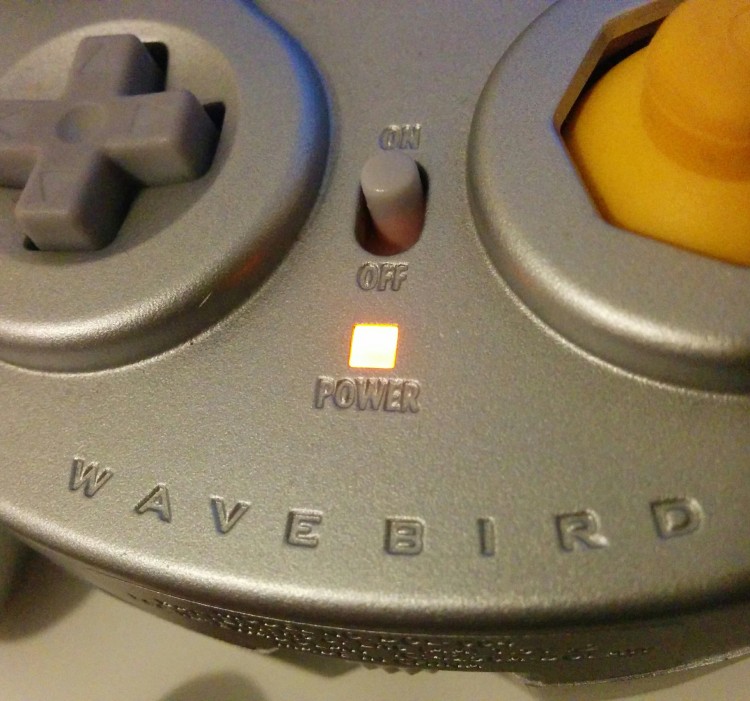
The faceplate part of the forepart shell (where the inked "Nintendo GameCube" logo is) stands slightly higher than its wired analogue to allow the antenna to fit. Considering of this, the kickoff button has to exist slightly taller to compensate. The bottom is besides extended to allow more circuitry, and to fit a on/off switch slot. The back shell also allows more infinite for the bombardment compartment, and the d-pad has a much better support within the shell than the wired controller, which makes it a much better experience to use. The front trounce also has extra markings aside from the "START/Pause": "ON" and "OFF" effectually the power switch, "POWER" under the LED and "WAVEBIRD" at the bottom.

The Grey WaveBird sports a set of lighter-colored gray buttons, stick and switches. Yous can also notice the small slice of clear plastic used to amplify the low-cal from the LED.
Every bit said to a higher place, here's the taller WaveBird kickoff button on the left, used to recoup the height of the faceplate. Also, yous can see the on/off switch here, which is located in between the D-pad and the C-stick. This is activated by the small rectangular slice of plastic you can see above. It is shown in the "off" position, the circuit is open.
six. Troubleshooting Common Issues
Once again, all the WaveBird and receivers are compatible. If your WaveBird does not connect to the receiver, in that location'southward a high take chances it's i of four things: The receiver's antenna, the bombardment contacts, or both rotary switches. Let'due south intermission it downwardly.
- If the WaveBird's orange LED lite on the front does non lite upwards when you put brand new batteries, it'due south most likely the battery connectors that are corroded. Yous need to unsolder them from the board and/or remove the lower one from the battery compartment (See the Battery Compartment section).
In that location'south a few ways to clean corrosion, but personally I use white vinegar. Soak the afflicted parts and brush it off. make certain to rinse them thoroughly afterwards, dry them off and solder them back on. If the orange LED lights up on the front when the switch is turned on, the current is going through.
- If the WaveBird turns on but can't connect to the receiver, it might be the receiver'due south antenna that is corroded. Open up the receiver and locate the antenna (See the Receiver or RF Info sections). If it'south covered in a brown chaff, take very fine sandpaper (2000 grit and higher up) and gently rub the surface until information technology's clean. Then, using rubbing booze, clean information technology. Permit it dry, reassemble and examination it with both units on the same aqueduct.
If the light-green LED on the forepart lights up, that means the receiver is connected to the controller and it should be working. Note that the antenna can get bad again, you lot might have to clean it once again in the future.
- If the receiver still does not low-cal up after those 2 steps above, it might be an result with the rotary switches for the channels. Information technology'due south peachy to have extra performance WaveBird hardware for this step, every bit if both units are defective, in that location'southward no fashion to tell.
The switch has a neutral position where the logic of the lath completely bypasses it (See the RF Info chart). That means the affected hardware volition nevertheless exist able to communicate through a specific channel. If the 3rd aqueduct works, the controller's rotary switch is defective. If the 11th channel works, the receiver'southward rotary switch is defective.
If you don't take a spare 16 step rotary switch to replace the lacking one, you lot tin can either keep it on the working channel, or since it's an effect with contacts corrosion, you tin effort to spin the switch really fast for near 20 turns. Ofttimes, that dislodges enough corrosion to make it work properly again.
If all of the above still does non fix your connectivity problems, make sure the controller PCB is non cracked or damaged. If the WaveBird or the receiver has been tampered with prior to the issues, I'm not sure I would exist able to help.
7. Resource and Traces
Resources
- Parts list from the FCC for the WaveBird: Website
- Shank'due south WaveBird Rotary Switch Guide: BitBuild Forum Thread
- Total receiver teardown: IFIXIT Guide
- Noble potentiometers catalogue: PDF Document
- Nintendo Gamecube Controller Protocol: Website
- The Mystery of the 900 MHz WaveBird
Traces
- ★ Madmorda's Wavebird Board Scans and Documentation: BitBuilt Forum Thread

Source: https://gccontrollerlibrary.com/guides/wavebird-internals-and-troubleshooting-guide/
Posted by: wilsonmarmyre.blogspot.com
0 Response to "How To Change Led In Wavebird Controller"
Post a Comment